
Stiga SD 98 ride-on lawnmower repair and mod
(Also includes how to seriously mess something up creating even bigger repair needs) When we bought our property we also purchased a lot of the equipment the previous owner had acquired. An integral part of that is the lawnmower tractor - total size is close to two acres and most of that is covered with grass. It’s a Hurricane HTG 98 SD, which is a model also sold under many other brands. In Sweden the most known one would probably be Stiga SD 98, but in the UK it’s likely an MTD. It has a Briggs & Stratton 17.5HP engine and does a pretty good job, we use it also to transport things around, collect leaves and tidy up the driveway gravel. A week ago it suddenly wouldn’t start. It’s been a bit finicky since we got it, but no matter what I tried it simply didn’t even engage the starter. This points to an electrical issue, right up my alley. Or so you would think. I have degrees in Mechanical Engineering and Software Engineering, but all the electronics stuff I blog about is all self taught. I also looked forward to tearing it down. Like other ride-ons, it has a safety switch where the engine cuts out immediately when it doesn’t detect a driver in the seat. This is all good and well, I really understand why, but when you have a huge lawn there’s just no way you can walk around in preparation for mowing, getting rid of all small rocks, large twigs and the constantly falling pears and apples now during the autumn. I really need to be able to keep it running while quickly moving things out of the way. Since I had a hunch that the reason it didn’t start was another one of the safety switches, I stripped it down and started to search for both where they originated, and where the mower made the decision to whether it was safe to engage the engine or not. Also, to figure out which one it was that was currently not enabling.
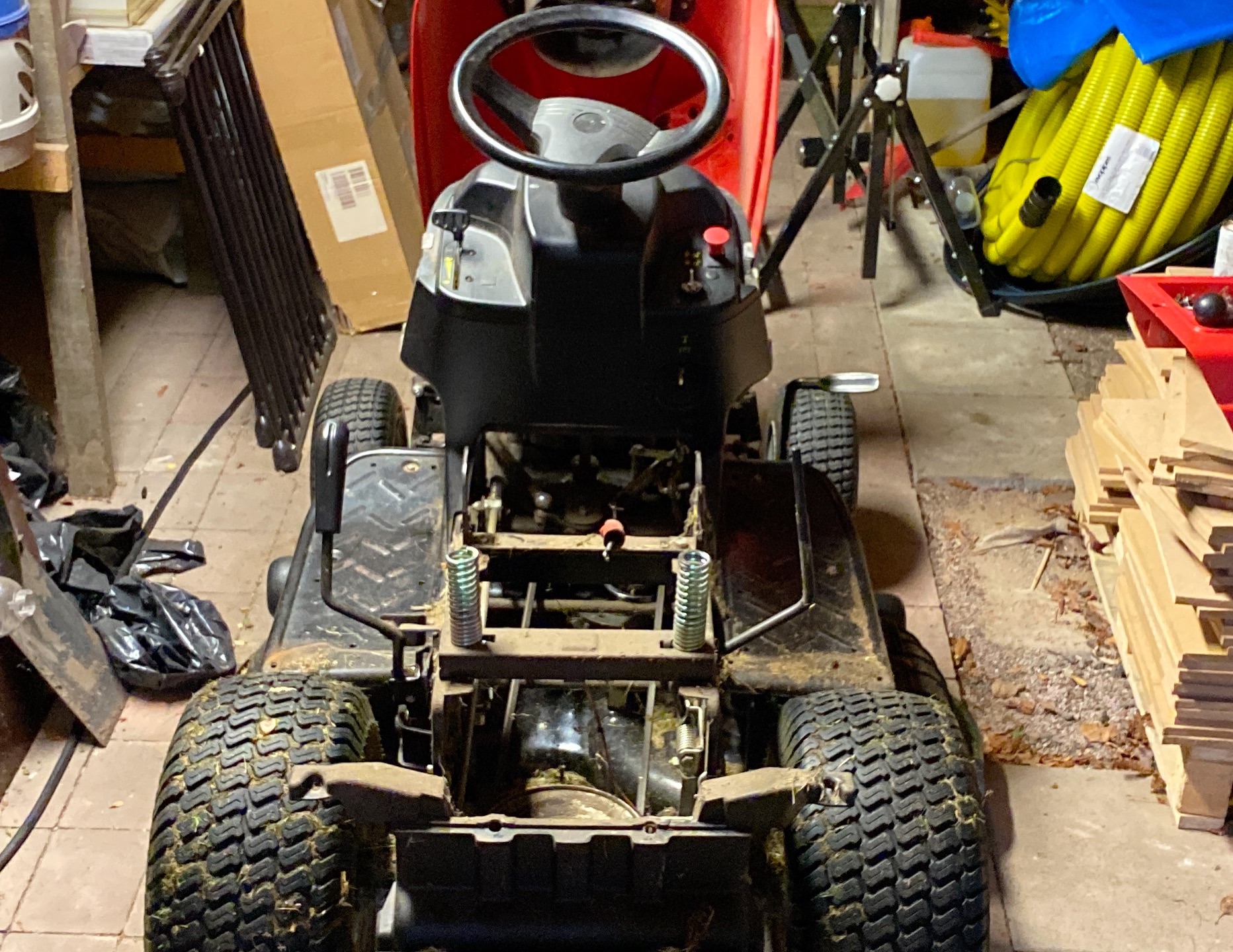
From experience, I knew that there were at least three safety signals that are all needed for the mower to start: Driver in the seat, gearbox in neutral and cutting blades not engaged.
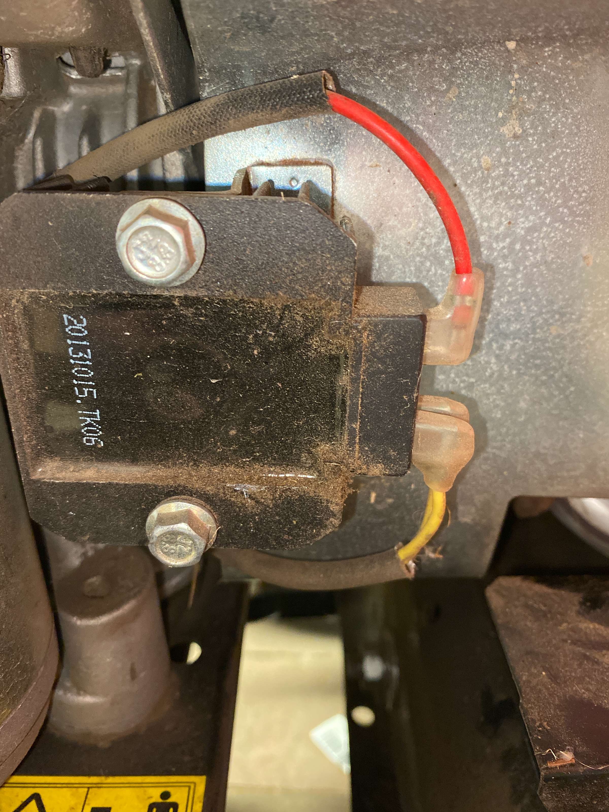
I decided to work backwards. This component is found next to the starter. Red is always 12V, the starter gets GND from a place not pictured, and I figured the two white cables would go to 12V when the key was turned to ignition. They never were. However, I could clearly hear a clicking sound as the key was turned to pre-ignition, so next my attention was turned to what that could be. (This component, btw, is a rectifier. It supplies DC power from the AC power generated by the engine, used to charge the battery. I was way off on its purpose there).
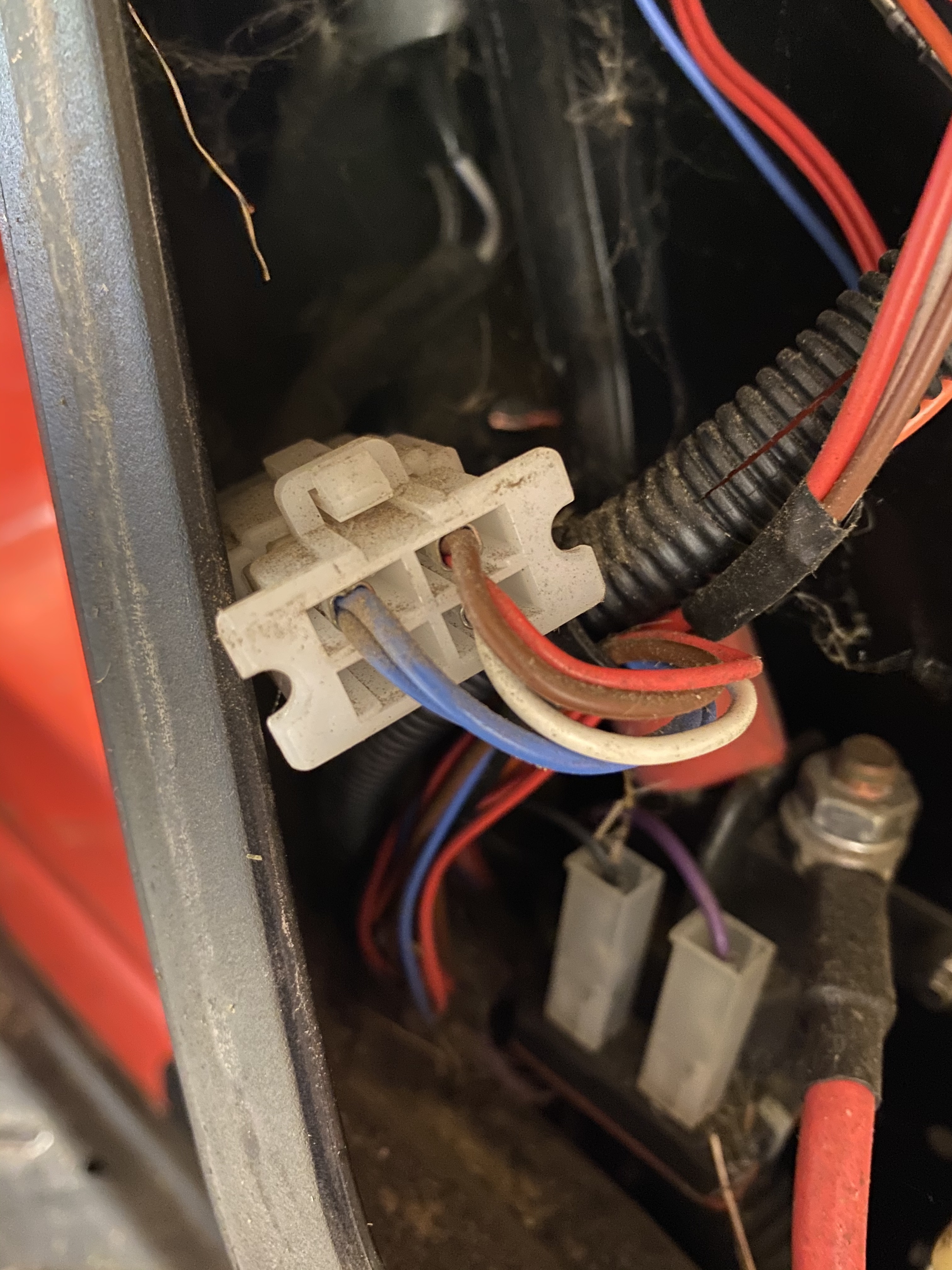
This is a breakout coming from the ignition key. White is 12V when the key is turned to ignition, red and brown are powered when the key is switched to pre-ignition. My model doesn’t have front lights, but from that I learned I can add them as a future mod. In the background you can see the solenoid, which is the component that does the clicking. It’s a relay, taking 12V directly from the battery with a high capacity cable, allowing current to pass through when the purple wire is powered (black is GND). And, indeed, the purple wire never went to VCC when the ignition key was turned. Since I had already seen that the white wire from the breakout did, I manually connected these together and verified that the starter engaged and the engine came to life. I now definitely knew that the issue was somewhere in when “white went purple”, which most likely was where the safety signals converged as well.
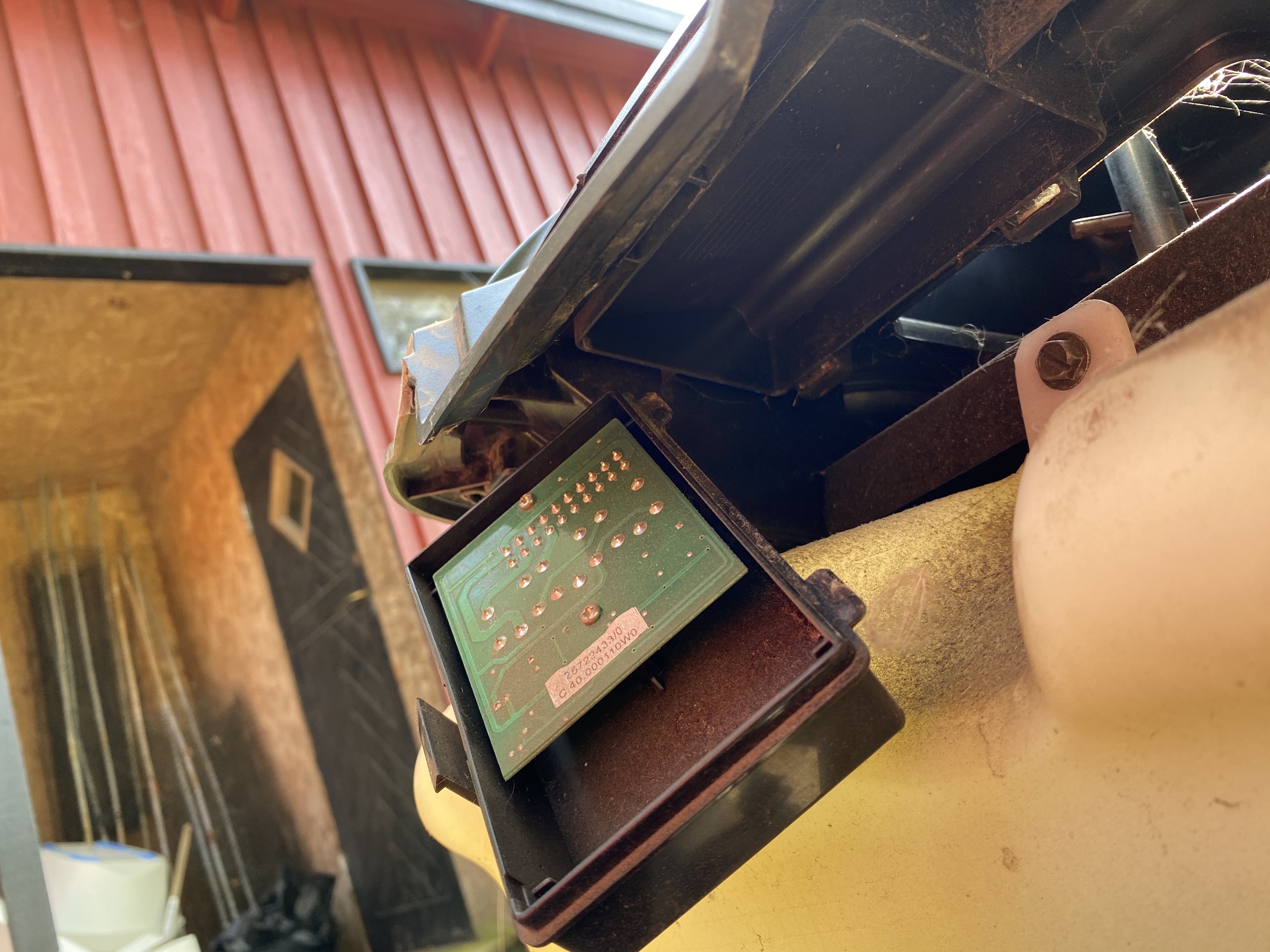
What do you know, that looks interesting. Beneath the steering wheel is a little black box with electronics. Opening it up, we can see some familiar colours:
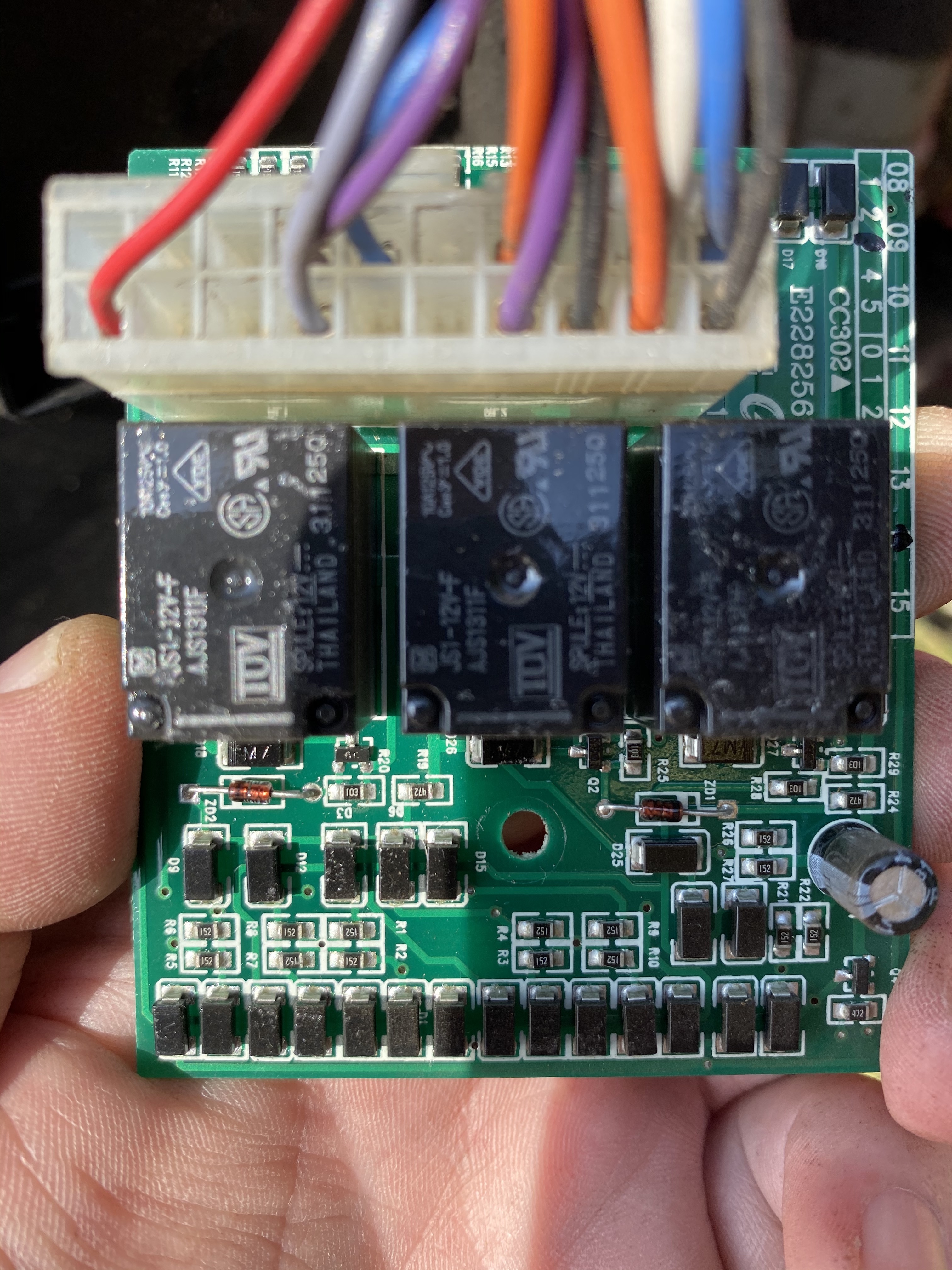
Red and blue in opposite corners are VCC. The larger gauge purple (yes, they are different) goes to the solenoid, the smaller gauge purple is a combination of the gear box signal and the driver seat signal. Blue’s ignition key and grey comes from the cutting blades engager. Maybe I also mixed them up when trying to remember - sorry. The two takeaways for my purposes is that I could measure these and see that the problem was with the push button enabling the cutting blades and also that I only had a combined signal for two of the safety conditions. And there’s no way I would want to mod the tractor so that it could be started while in gear. I removed the button, separated the connectors below, cleaned out any corrosion with electronics cleaning spray and put it back together. Now it was time to get to work on that driver’s seat safety switch I had in mind. I wanted to hide (we have kids) a little toggle switch somewhere so I could selectively have the function enabled or not. Interestingly, when searching for if someone had done this before, I only found videos from other tractors where this wire was easily spotted underneath the seat - but that isn’t the case here. It turns out, the detection is done underneath the bodywork, where the springs attach to the frame.
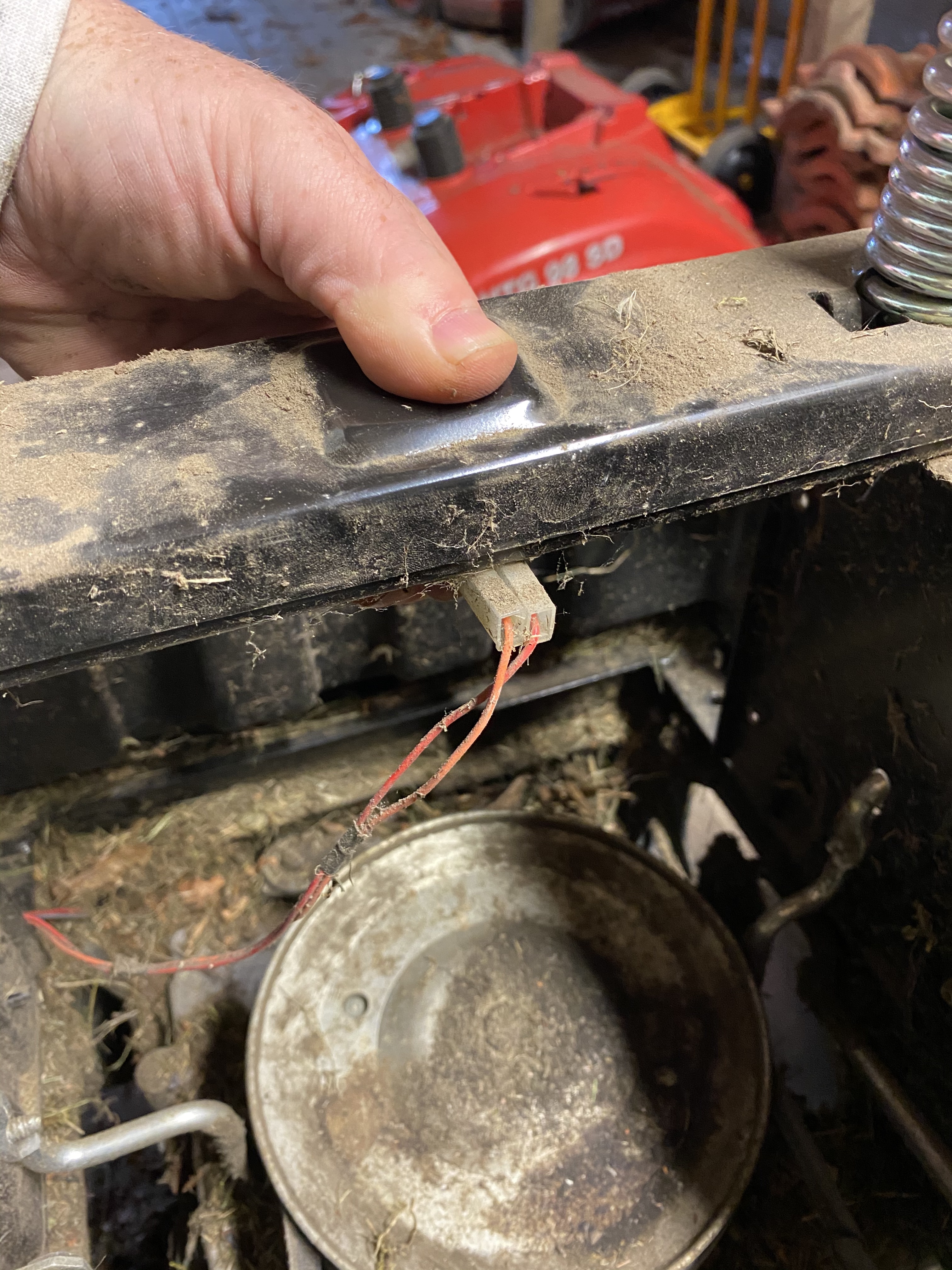
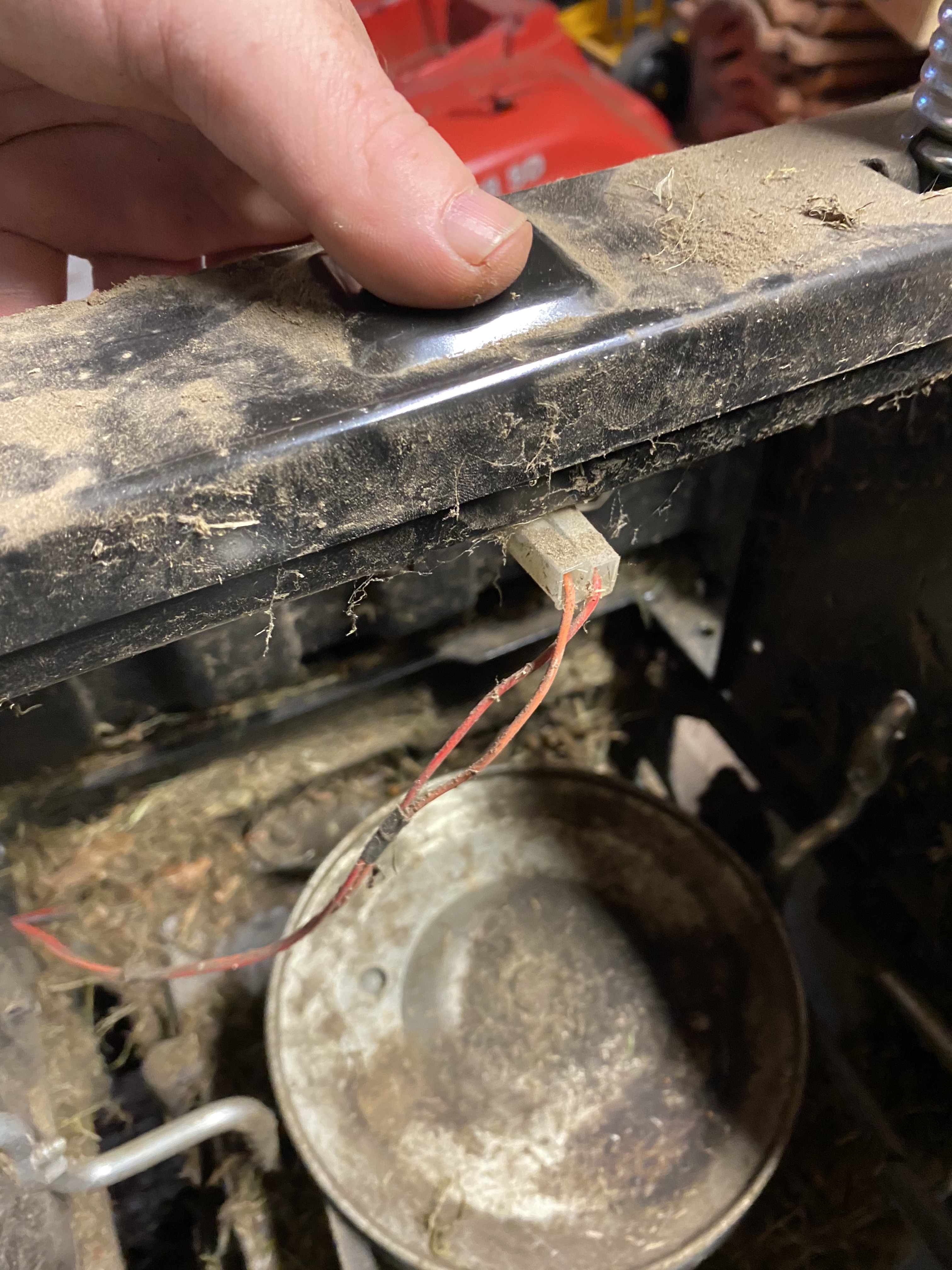
Alright, there’s the connector. VCC on one wire, and when the driver is seated it simply connects them together. Wiring up a switch here is easy, connect in parallell and short them together for the override function. Uh oh.
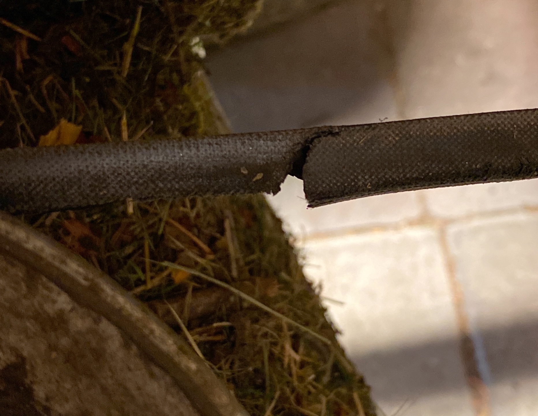
That’s … not good. That’s the main drive belt from the engine to the gearbox. Somehow I had managed to catch this just in time before it broke completely - and with everything torn down already! I stopped thinking about the override switch and went to order a replacement belt. *a few days later* Ok. So, I had already changed the cutting deck belt some weeks earlier, so how hard could it be? The belt simply wraps around some pulleys and then …
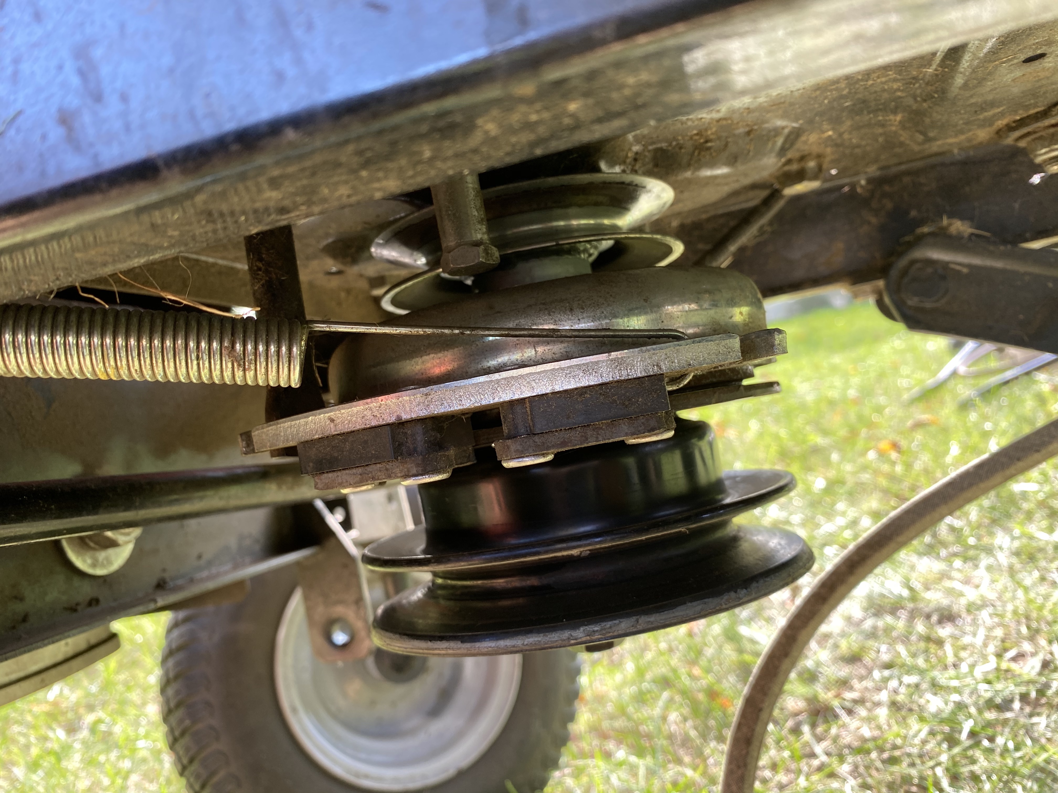
… hmm. It needs to get to that top pulley. And there’s something in the way of that, so it seems I would need to move the lower pulley and that other thing out of the way first.
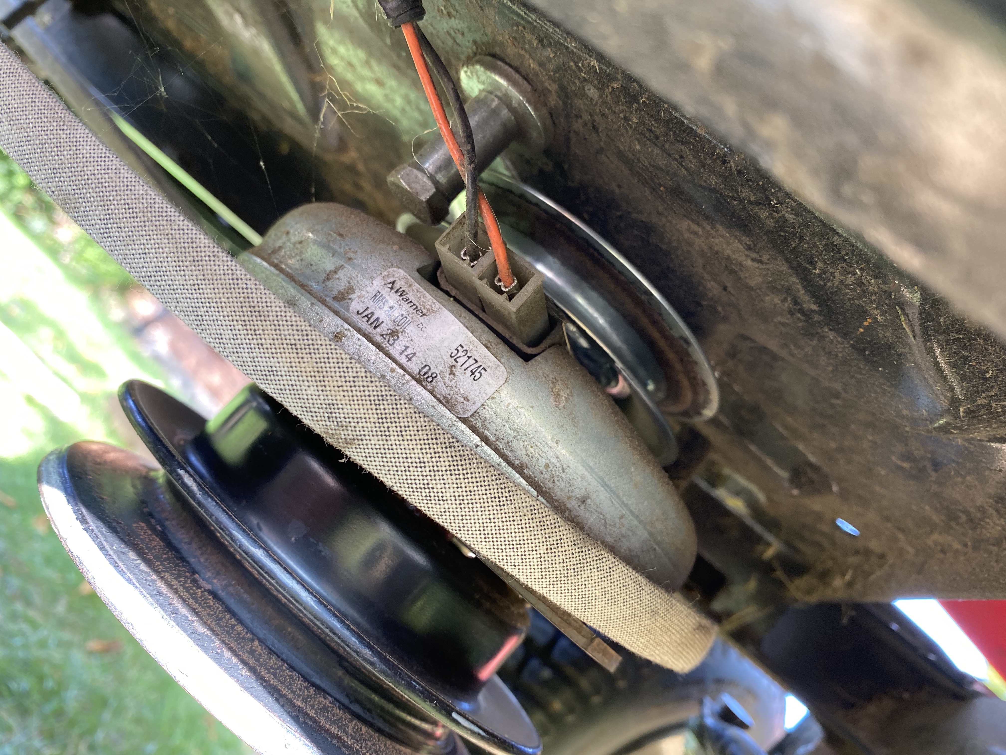
That ‘other thing’ is a PTO brake, I learned. When engaged it magnetically engages a brake on the drive shaft. Good stuff. I watched some more youtube videos and all I had to do was to remove the nut and it and the pulleys should slide down. Well, yeah. In the ideal world of Youtube. No matter how hard I pulled, even with careful use of a lever (so as not to bend the shaft) they were completely stuck. This is where I would go down the wrong rabbit hole and seriously start messing things up. I blame lack of sleep, overwork, having three small kids and the phase of the moon. It seemed possible to attack the shaft from the other end, so I opened up the engine cover and pulled the nut from the flywheel. My thinking here was that if I removed the flywheel, somehow that would aid me in just moving the shaft the centimeter or so needed to thread the drive belt around the guides. But just as the pulleys, the flywheel didn’t budge. And so I turned my attention to four screws on the side of the flywheel. Now, I’m of the mindset that most things you disassemble you can put together again, so I didn’t spend any time thinking about what they could be for - just that they might be the ones stopping my progress. One of the bolts came out easily, but the next three just immediately sheared. So I started drilling them out, which worked well for one of them but not the other. At this point, I did notice that when I turned the flywheel, there was a noise I hadn’t heard before. Also, I started thinking about my knowledge of, and lack of knowledge of, flywheels. I decided the stop messing with the flywheel, and instead see if there might be some youtube videos showing me how to pull pulleys. I had searched for how to replace a drive belt, of course, but none of them had this PTO brake and they all had it easy where they could just slide the belt either over the lower pulley, or their models had engine mounts that could be moved back and forth. Some better search terminology and off to the hardware store to buy a three-armed puller . It took all of five minutes to then get the pulleys and PTO brake off. I had spent the better part of a day on this problem already, so I was filled with joy. Another five minutes and the belt was in place. Some quick connections and the battery temporarily in place and it was time to start the engine. I wasn’t too bothered with the two bolts I had removed from the flywheel, it seemed securely in place and I had also bought replacement bolts I could put back. The starter engaged and I heard a big clonking sound and that was it. The positives: I had fixed the original problem, and I had a new drive belt. The negatives: The engine was dead. Now I decided to freshen up my knowledge of flywheels. My teenage years as a souped-up thirteen-horsepower-moped gangsta all came back to me and I realized I had most likely loosened magnets on the inside of the flywheel, and they were now grinding down getting stuck. I had my finger on the button for a new 200 euro flywheel. Went to sleep. The next morning I tried to use the puller to lift the flywheel, but that was a no-go. There are two threaded holes for some speciality equipment for this, but it wasn’t something I could find in my local stores and I was getting real tired of this tractor. I found some bush-fix suggestions where you levered some slight tension upwards and then whacked the shaft (protected by the nut) with the biggest hammer you have. Well, I have an enormous sledge hammer. Five whacks later, and the flywheel came off.
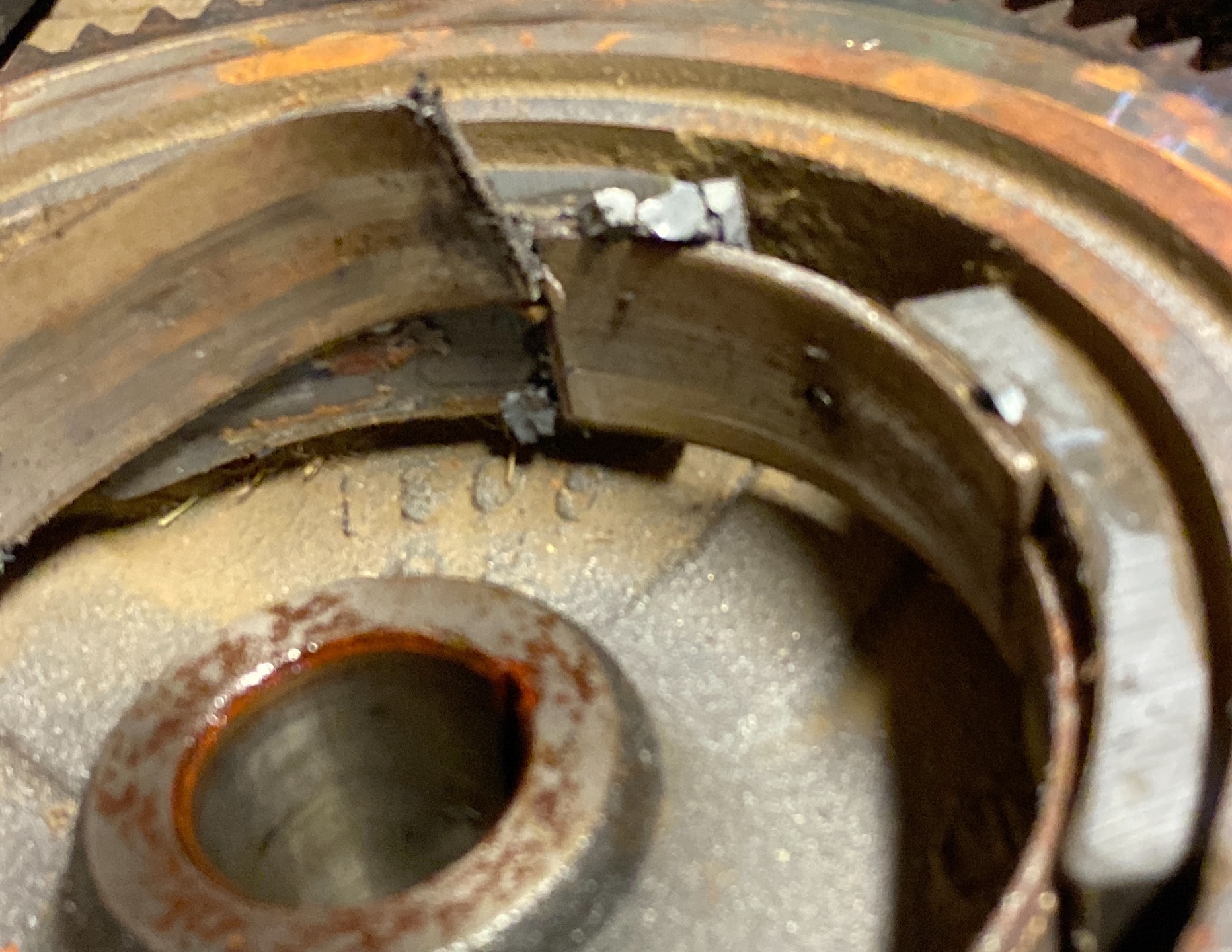
Positives: My restored knowledge about flywheels had lead me to the correct conclusion. Negatives: Those metal plates protecting the magnets were bent out of their original shape - and these rotate around fixed magnets at the tiniest of surface to surface gaps needing to be pretty perfect to work.
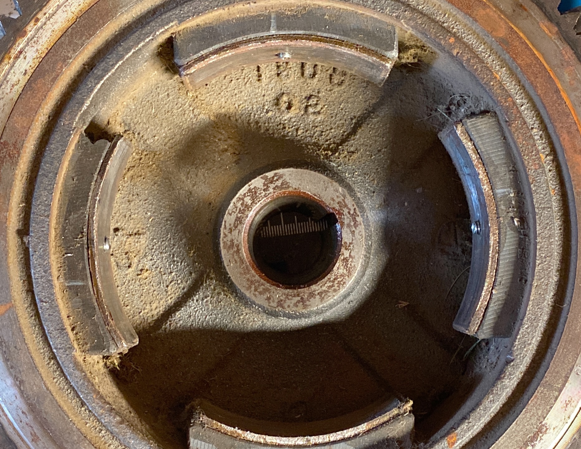
A lot of careful whacks and taps with a hammer later, and some drilling, I had managed to produce what actually looked pretty good. This picture was taken before I dremeled the bolts down to level though, but you get the idea. I mounted everything back together and was greeted by a perfectly running engine. You should see the grin on my face. I had messed this up - badly - but managed to save it. Alright, back to that safety switch.
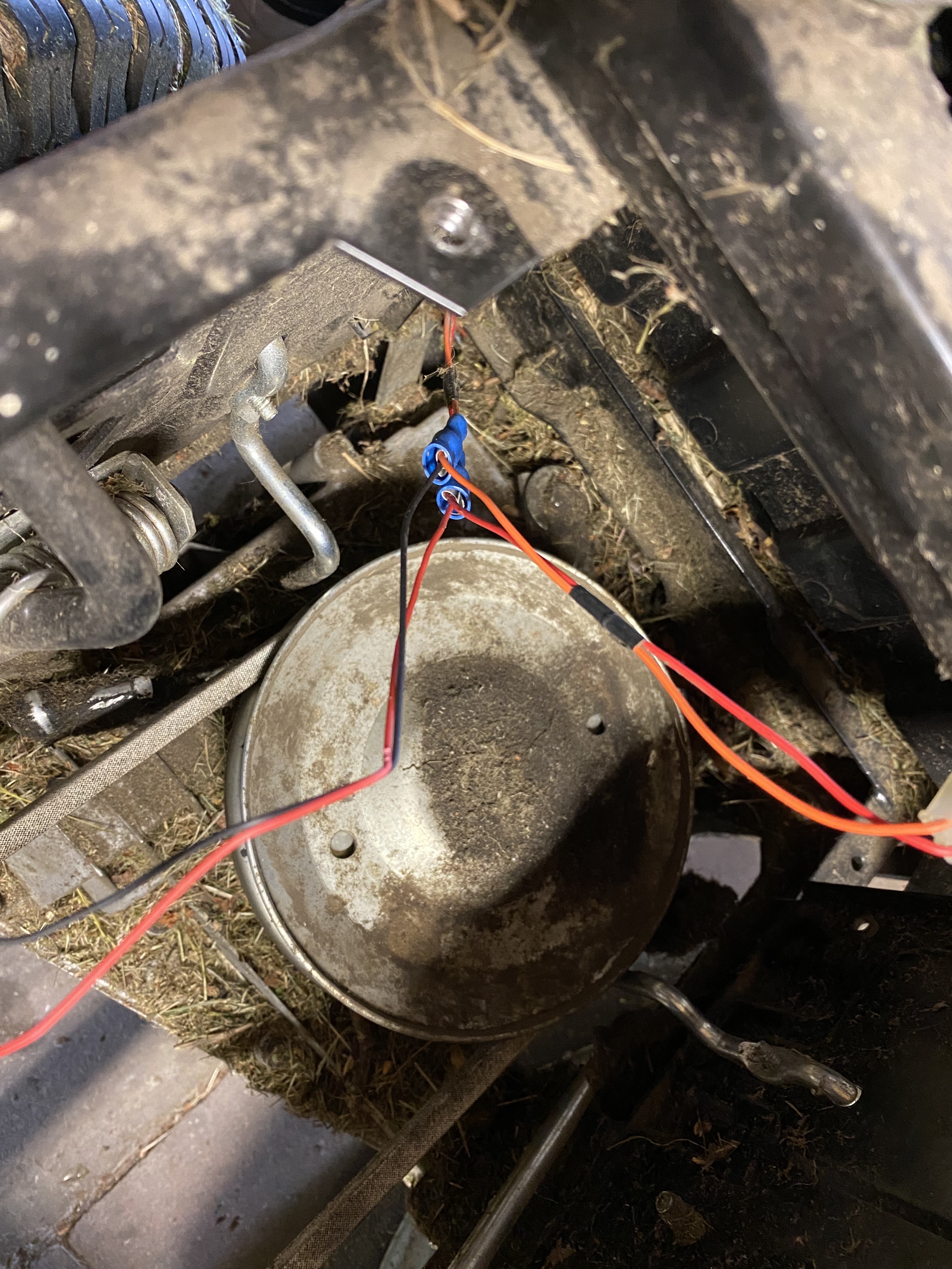
This is where I decided to connect up my switch in parallel. If you inspect your SD 98 from the right side, you’ll see some wiring tubes coming from the rear to the middle. One of them has three wires: red, orange and gray. Red is VCC, orange is the seat safety and gray is the gearbox safety. That’s probably the easiest places to do this mod, not requiring any teardown of bodywork at all - but hey - I had already done it.
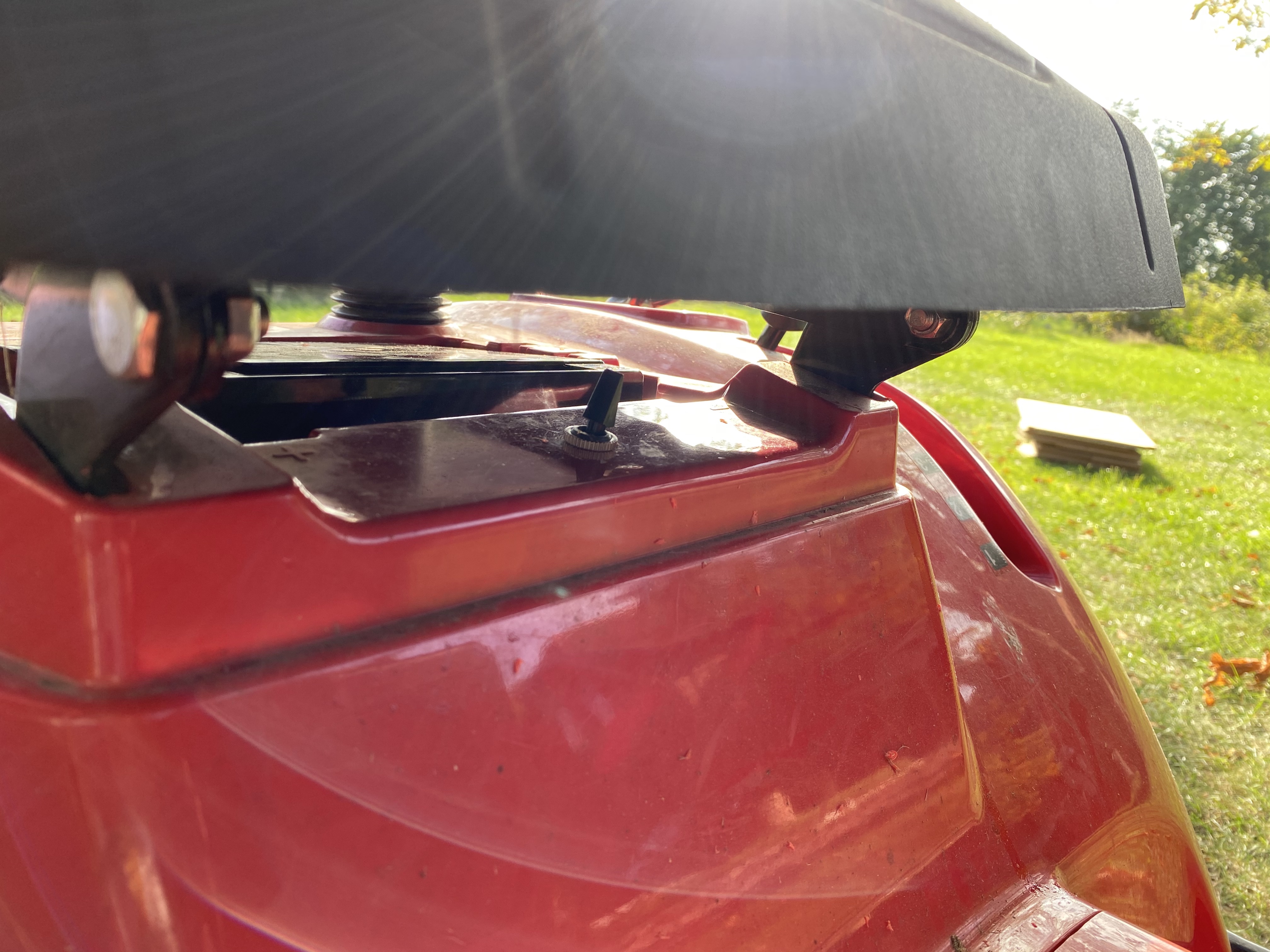
… and here’s how it looks, finally mounted in place. Easily reachable if you know where to look for it, and hopefully something the kids won’t figure out until they’re old enough to be trusted with it. Oh, and the mower runs better than ever. I took the time to lubricate wherever suitable as I went along, and I cleaned out a lot of assorted junk from various places as well. I even think the motor sounds better, but that’s maybe wishful thinking. -“Troed, you should have your own Youtube channel for all of this instead of blog posts!” No thanks. I absolutely hate having to wade through someone waffling about when all I want is to quickly get to what the solution I searched for is. If you came here looking for how to mod the driver’s safety on a Stiga/HTG/MTD/etc - aren’t you glad you didn’t have to? :)