
Atari ST drive A and B swap
It’s retro computing time again! As part of my quite extensive rebuild of one of my Atari STE machines I want to have both an HxC SD floppy emulator as well as the original floppy disk drive mounted internally in the machine at the same time.
While that in itself is just a question of making a cable that supports both, another problem quickly arises. In most cases you would want the machine to boot off the HxC (drive A:) and the internal floppy would then be drive B:. However, in some cases there’s clearly a point in booting off the internal floppy instead - and for that it has to be drive A:. In real Shugart floppy speak this amounts to the drive select signals, DS0 and DS1. On a modern ST both are available on the internal cable, and one (DS0) on the external. What we want is obviously to mount a switch that will swap these two signals at will.
This is a solved problem. DS0 originates from pin 20 of the YM 2149 sound chip (really!) and DS1 is on pin 19. Cutting these two pins and then soldering two cables from the motherboard to the middle pins of a DPDT (dual pole, dual throw) switch and two cables from pin 19 and 20 to one side, crossed over to the other side, will do. It’s also possible to achieve a swap between an internal floppy and an external drive without cutting pins - some prefer to avoid that - but it won’t swap the two internal signals.
Yesterday I really wanted to avoid cutting pins - but at the same time I needed a way to switch not only internal and external, but the two signals on the internal cable as well. I thus had to innovate a bit, and this post details the result. All pictures from a regular STE - I haven’t looked into what’s different on a regular ST or Mega model.
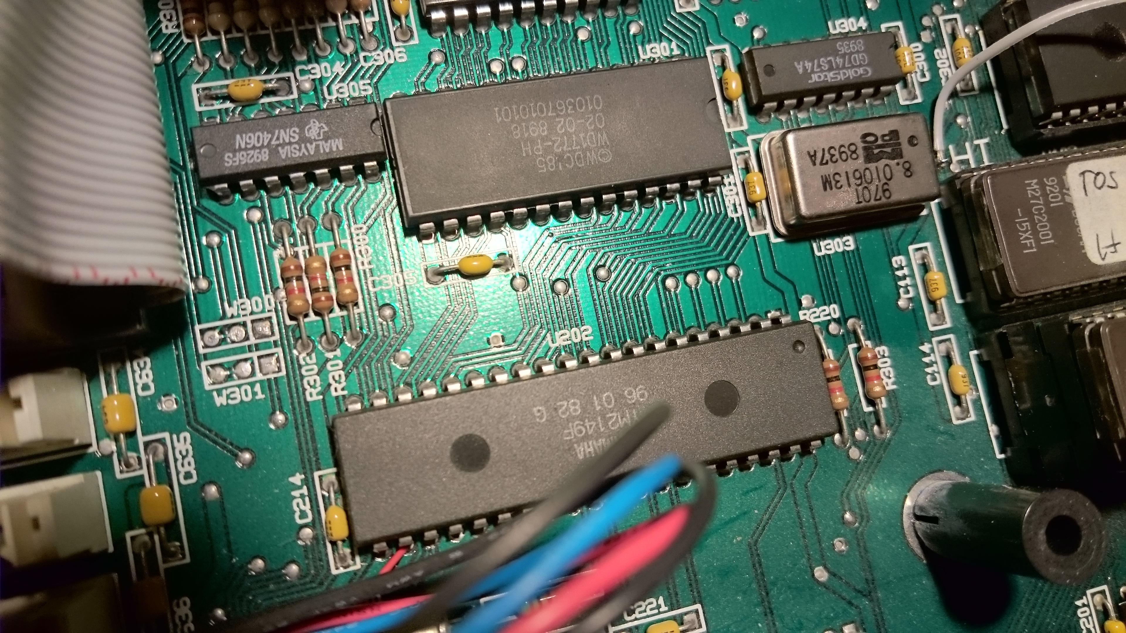
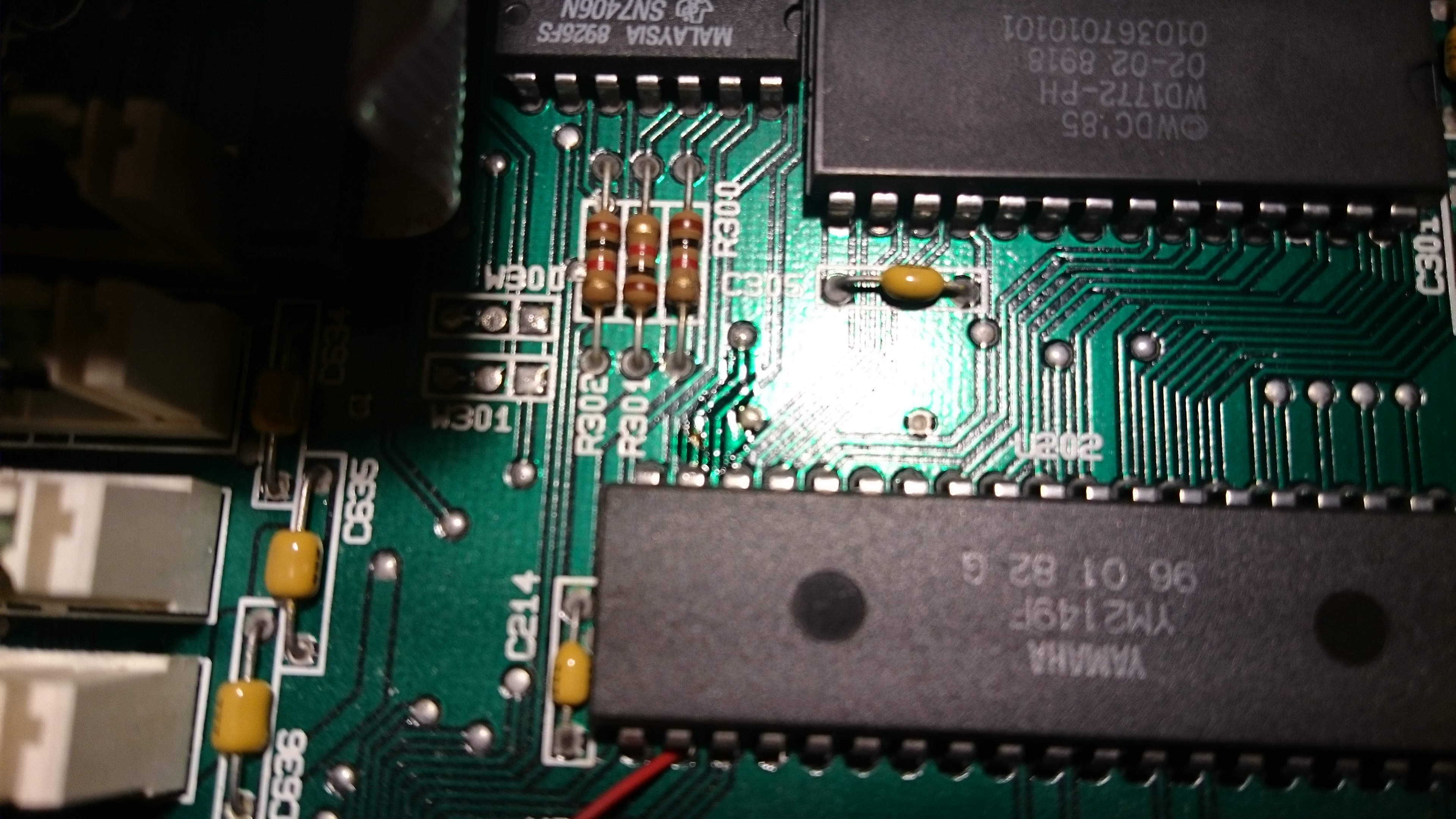
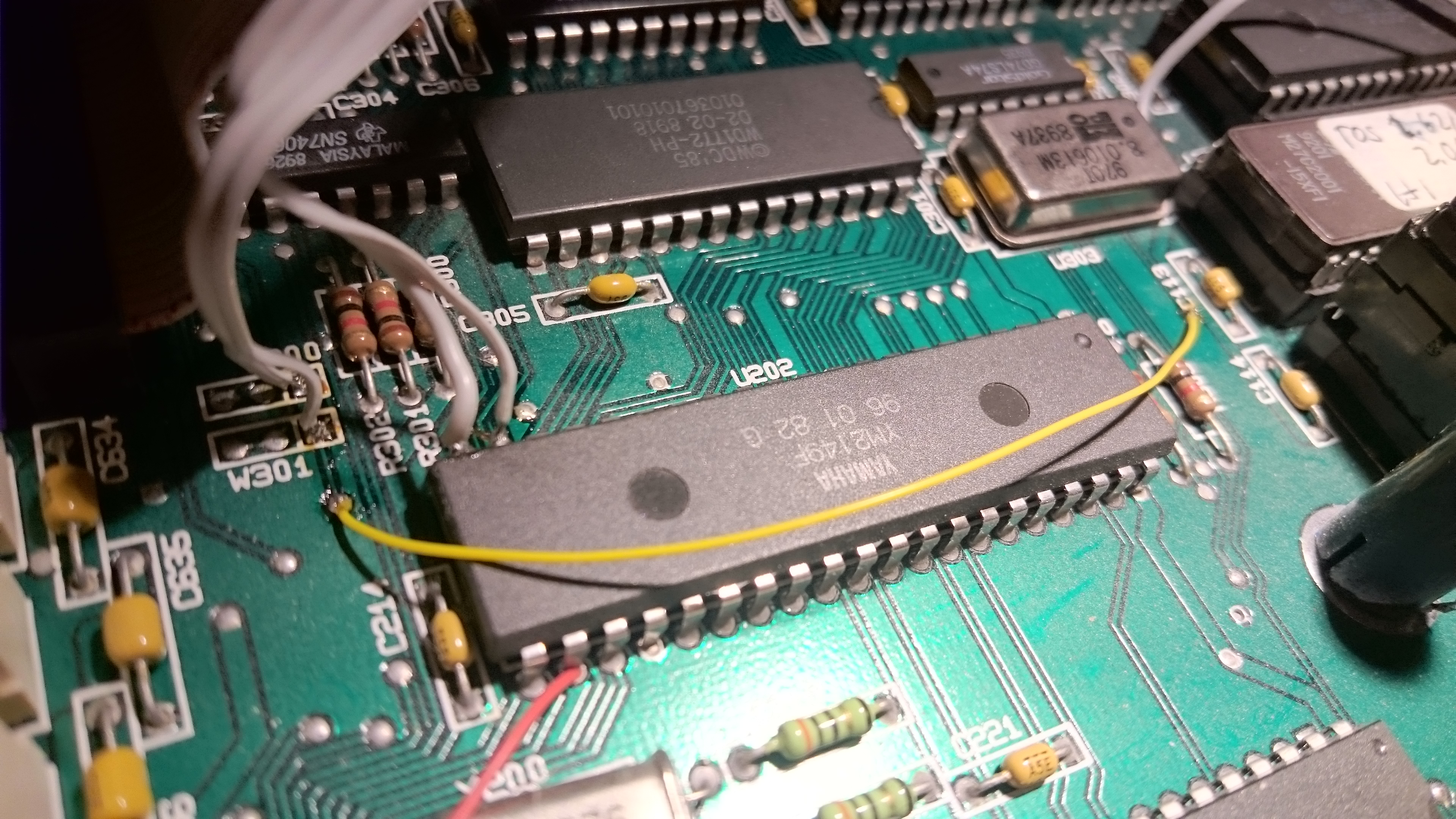
This is our area of interest - before any modifications have been done. Pin 20 and 19 of the YM 2149 soundchip are clearly visible (upper left of the chip from this angle) - and you can also see that pin 19 can be traced to a via. There’s no visible trace from pin 20 - leading us to conclude that it’s on the bottom side of the motherboard. Also note the three solder points named W300 and W301 respectively (square solder pad is pin 1 on each) - these are very much involved in what we want to do. DS1, pin 19, is available on W300-1 and DS0, pin 20, is available on W301-1. We see that W301-1 can be traced to a via just below it as well.
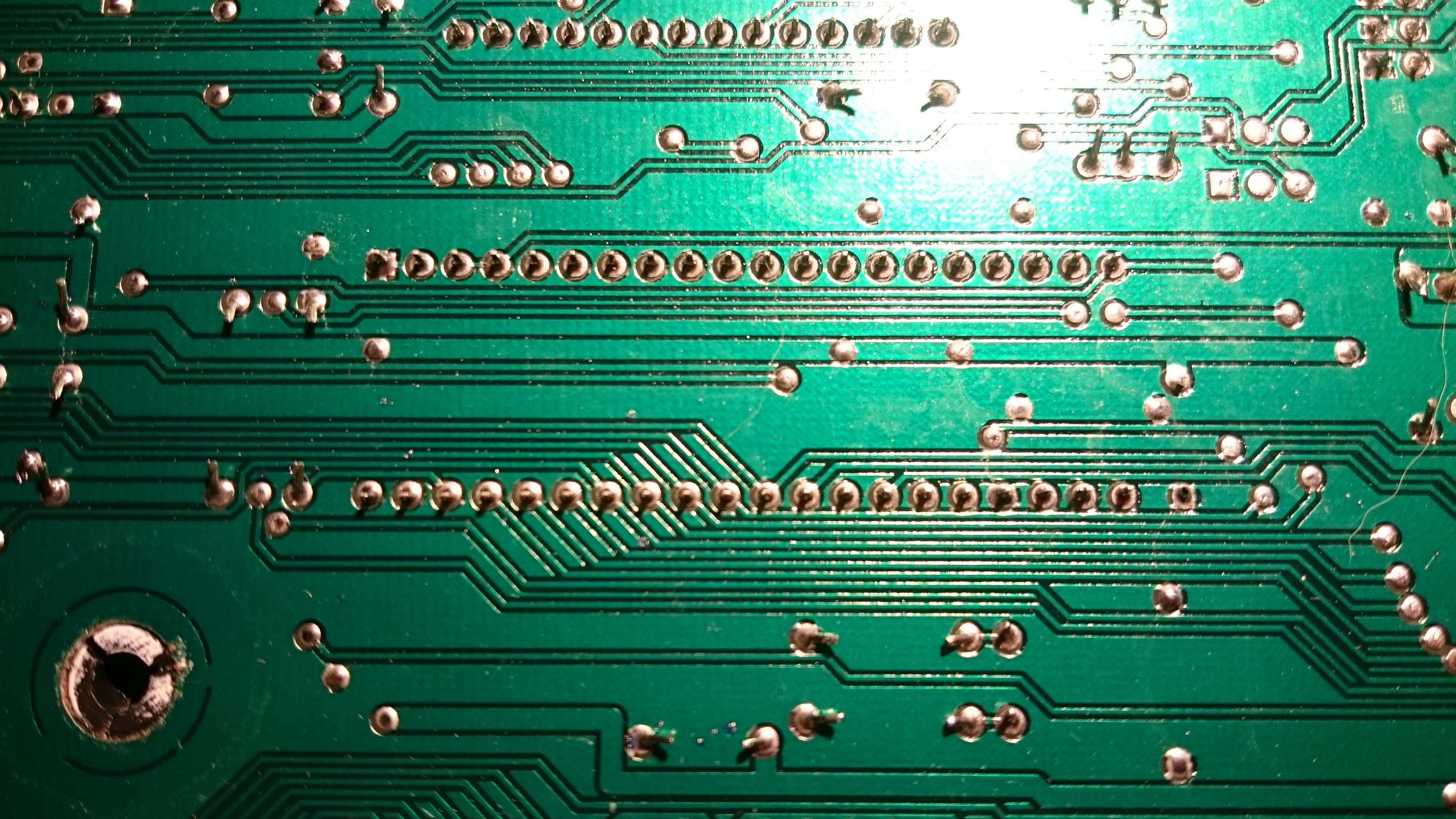
Turning over the motherboard we can see that pin 20 is indeed connected to the same via we just traced from W301-1 - but it’s also traced to another via on the other side of the chip! This second via is found topside at the ‘C’ in ‘C113’. With this knowledge we can now conclude that if we do not want to cut the actual pins 19 and 20 of the sound chip, we have a few cuts to make to traces on the motherboard. We must cut both traces originating from pin 20 on the bottom side of the motherboard, before the vias, as well as the trace to the via topside from pin 19.
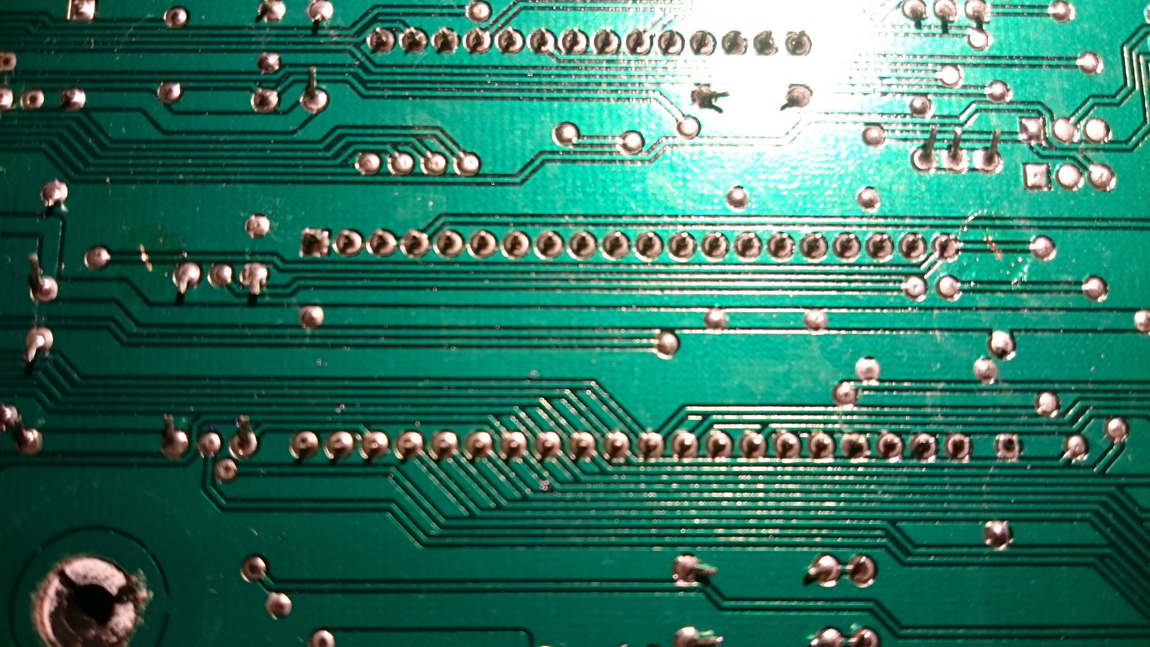
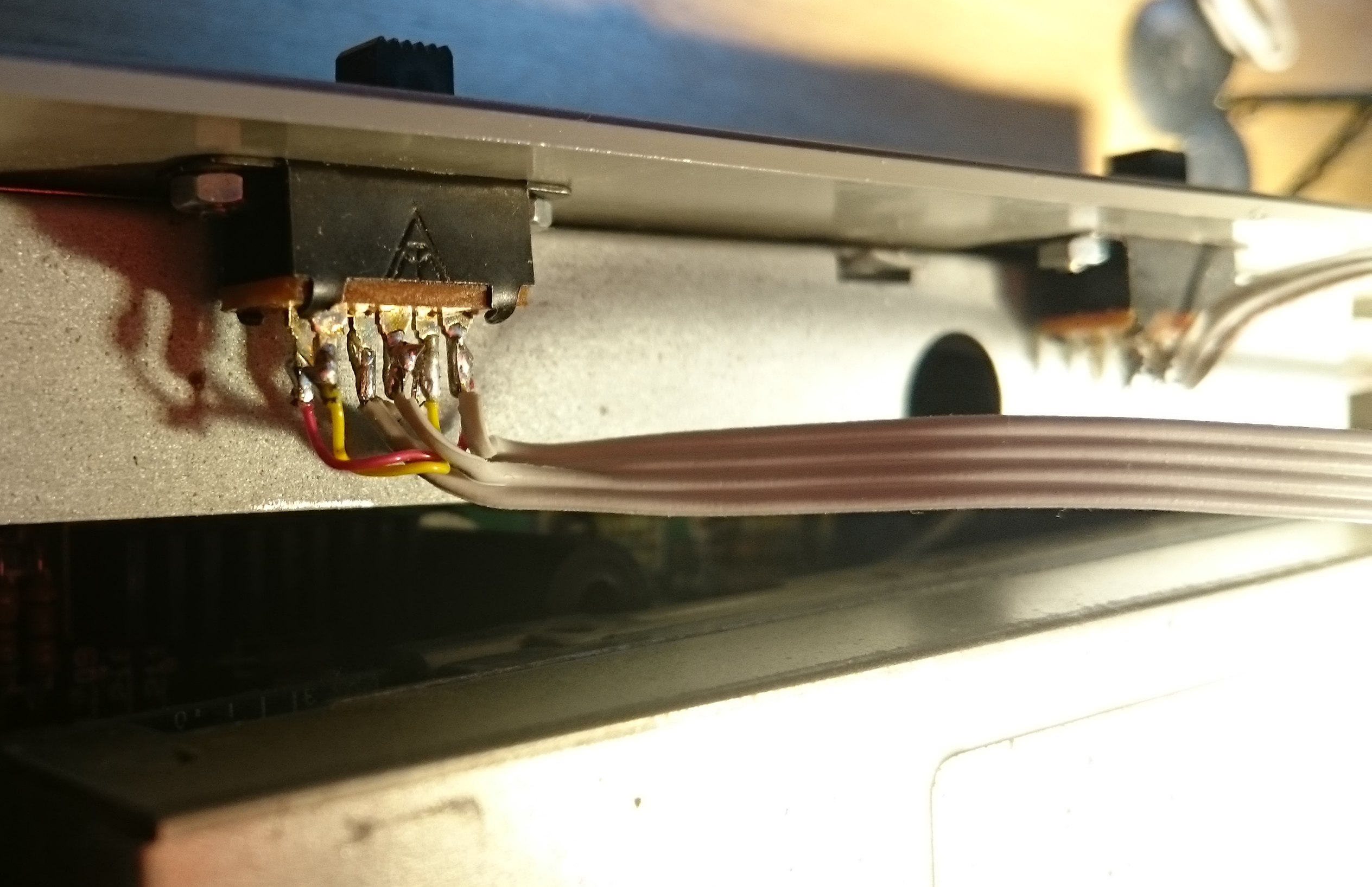
Make sure to measure resistance with an Ohm meter to know when you’ve cut through the traces, and don’t cut off anything else. There’s plenty of space on the bottom side of the motherboard, a bit less topside. Once we’ve done these cuts, we’ve effectively severed the connections of the originating signals on the sound chip pins from where they go on the motherboard (internal cable as well as external port). However, we’ve also severed the connection between the two different directions pin 20 went off to - so we have to repair that topside. The easiest way is to solder a wire between the vias we just traced it to. We also have to mount the wires to our switch, of course. We pick up the signals directly from pin 19 and 20 - to the end points of our switch (crossed over at one of the sides). We then solder wires from the middle pins of the switch to W300-1 and W301-1. And we’re done.
This will switch not only the signals on the internal cable - but also swap internal and external. It’s effectively exactly the same as what’s achieved by cutting the pins off the chip as described in many places on the web.
So why didn’t I just do that? Well. I seem to have misplaced my side cutter. So .. there. Enjoy.